Wednesday, October 13, 2010
Active AM Radio Antenna Amplifier / Preamplifier Circuit
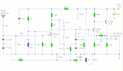
The antenna amplifier circuit has a part count of about 40, using the following active parts: 2 NPN transistors (BC548's), 1 MOSFET (BF981), 2 Varicap diodes (KV1235), as well as a 6v2 zener-diode. there is and a 330uH (micro Henry) inductor / coil, which can be modified for operation on other frequency bands.
Designed to work with a telescopic whip antenna, the amplifier circuit operates in the typical AM / MediumWave band of 550 - 1650 kHz (kilohertz), with a power requirement of 12 Volts DC. The circuit also has a gain control feature, so weather signals can be amplifier more, if need be. This amplification alteration is provided via, RV1
The amplifier circuit's output impedance is 50 Ohms, which is the standard for all of radio receivers, so it ought to work well along with your AM receiver.
Notes
This circuit is designed to amplify the input from a telescopic whip antenna. The preamplifier is designed to cover the medium waveband from about 550Khz to 1650Khz. The tuning voltage is supplied via RV2, a 10k potentiometer connected to the 12 Volt power supply.
RV1 is the gain control allowing weak signals to be amplified or strong signals to be attenuated. The control voltage is applied to gate 2 of TR1, a dual-gate MOSFET, the signal voltage applied via gate 1; the input signal being double tuned via the 330uH coil and the two KV1235 varicap diodes at the MOSFET's input and by the same components at the BF981 MOSFET's drain terminal. Both tuned circuits provide high selectivity across the entire tuning range. To aid stability the MOSFET stage is fed from a 6.2V zener stabilized supply.
Advertisement:Designed to work with a telescopic whip antenna, the amplifier circuit operates in the typical AM / MediumWave band of 550 - 1650 kHz (kilohertz), with a power requirement of 12 Volts DC. The circuit also has a gain control feature, so weather signals can be amplifier more, if need be. This amplification alteration is provided via, RV1
The amplifier circuit's output impedance is 50 Ohms, which is the standard for all of radio receivers, so it ought to work well along with your AM receiver.
Notes
This circuit is designed to amplify the input from a telescopic whip antenna. The preamplifier is designed to cover the medium waveband from about 550Khz to 1650Khz. The tuning voltage is supplied via RV2, a 10k potentiometer connected to the 12 Volt power supply.
RV1 is the gain control allowing weak signals to be amplified or strong signals to be attenuated. The control voltage is applied to gate 2 of TR1, a dual-gate MOSFET, the signal voltage applied via gate 1; the input signal being double tuned via the 330uH coil and the two KV1235 varicap diodes at the MOSFET's input and by the same components at the BF981 MOSFET's drain terminal. Both tuned circuits provide high selectivity across the entire tuning range. To aid stability the MOSFET stage is fed from a 6.2V zener stabilized supply.
To drive low impedance (50 ohm) receivers, the medium output impedance of the BF981 stage is enhanced by the composite amplifier made from Q2 and Q3. Q2 is operating in common emitter boosting voltage levels by just over 2, Q3 is operating in emitter follower providing the circuit with low output impedance.
Finally this active antenna can be used on other bands by changing the values of the 330uH coils. To perform on multiple bands switches or relays can be used to change the value of the coils.
Subscribe to:
Post Comments (Atom)

No comments:
Post a Comment
Note: Only a member of this blog may post a comment.