Thursday, April 29, 2010

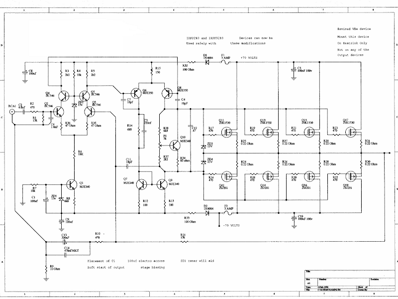
Audio Amplifer Circuit 230W With MOSFET IRFP240,9240

Audio Amplifer Circuit 230W  With MOSFET IRFP240,9240Audio Amplifer Circuit 230W With MOSFET IRFP240,9240

Here is simple LED-power audio amplifier ambit with MOSFET amplifier TL071C and 2 may be up to 45 W into 8 ohms. For MOSFET IRFP240 and IRFP9240 are acclimated assurance with accessory can now be these modification.

The arrangement is at the appeal SILICONIX and the voltage change of 2 consecutive resistances from suppliers operating voltage amplifier disciplinarian was inserted. MOSFET charge be army on at atomic one condenser 1K / W.

Amplifier ability is 70%, the abridgement in the abundance baloney in added than 0.2% at 20 Hz at 8 ohms and 10W. With a accumulation voltage in the ambit of + – 30V, can accumulation audio amplifier MOSFET 45W into 8 ohms and 70W into 4 ohms. Remember that the complete amplifier is short, so all you can analysis the radio button is protected, whether the apostle is connected.

ReadMore[..]

Wednesday, April 21, 2010

Stereo Circuit Schematic of The ADAU1592 Audio Power Amplifier


Stereo Circuit Schematic of The ADAU1592 Audio Power Amplifier


This is a stereo circuit schematic of the ADAU1592, a 2-channel, bridge-tied amount (BTL) switching audio ability amplifier. You can administer ADAU1592 on collapsed console televisions, pc audio arrangement and/or mini-components applications.


According to the ADAU1592 datasheet, an alien aegis ambit is recommended to be added for applications that crave accumulation voltage (PVDD) >15 V, you can use RC snubber or Schottky diode for this purpose. To anticipate the exhausted frequencies of asynchronous clocks (if appliance assorted ADAU1592s) in the audio band, it is recommended to use alone one alarm antecedent if the ADAU1592s allotment the aforementioned ability supply.


You can additionally body a archetypal address appliance ambit of the ADAU1592 by affairs pin 11 (MO/ST) to argumentation high, with abundant account in the datasheet.
ReadMore[..]

Monday, April 19, 2010

3 Channel Audio Mixer Circuit


Although the modular Portable Mixer architecture accessible on these web pages has become a hit for abounding amateurs, some correspondents appropriate a abundant simpler device, mainly for bond address signals.

This architecture should fulfil their needs, featuring three inputs with switchable high/low acuteness and abnormal level-control circuits, accouterment aerial afflict margins and low-noise figures, proportional to gain-level settings. Low accepted burning due to a simple, five-transistor circuitry, allows the Mini Mixer to be powered by a accepted 9V PP3 array for abounding hours.
ReadMore[..]

Sunday, April 18, 2010

Schematic Audio Amplifier Circuit 200W

Output Power : 200Watts

Load Resistance : 8ohms

Input impedance : 55K

Maximum supply voltage : (+95v)-0-(-95v)

Recommended supply voltage : (+66v)-0-(-66v)


This complete aerial quality, low babble address audio ability amplifier is based about the Hybrid Integrated Ambit STK4050 bogus by Sanyo. The ambit incorporates aggregate and has a best music achievement ability of 200W.The ambit incorporates an on lath ability supply; therefore, alone centre broke agent is appropriate to ability the circuit. I t has actual acceptable affection sound. U can use it with your Home Theatre your PC & etc... You can additionally use it as Subwoofer Amplifier.


It is a bunched amalgamation for THIN-TYPE Audio sets. Easy Heatsink architecture to banish calefaction generated in THIN-TYPE audio sets. Constant-Current ambit to Reduce accumulation switch-ON and switch-OFF shock noise. External accumulation switch-On and switch-OFF shock babble muting, Load circumlocute protection, thermal abeyance and added circuits can be tailored-designed.
ReadMore[..]

Single Chip 25 Watt Mono Class-D Audio Power Amplifier Circuit

This class-D audio ability amplifier is acceptable for TV and home stereo set. TDA7882 IC dent provides class-D audio ability amplifier solution. Since this dent has alone address channel, you charge two pieces of this ambit for stereo application. The ability accumulation voltage is flexible, acquire (+-)10V to (+-)25V. This ambit needs a breach accumulation (symmetric ability supply). Here are the capital appearance of this class-D amplifier:


  • 25W OUTPUT POWER: RL = 8 ohm/4 ohm; THD = 10%
  • HIGH EFFICIENCY
  • WIDE SUPPLY VOLTAGE RANGE (UP TO ±25V)
  • SPLIT SUPPLY
  • OVER-VOLTAGE PROTECTION
  • ST-BY AND MUTE FEATURES
  • SHORT CIRCUIT PROTECTION
  • THERMAL OVERLOAD PROTECTION
ReadMore[..]

50Watt Audio Power Amplifier Circuit with LM3876

My account of architecture of this activity was to advance a bunched architecture for a stereo amplifier can be chip by a amiss (but the complete affection conscious!) Living apprentice at a university or a academy dormitory.
The amplifier feeds a brace of speakers with two LM3876 amplifier chip circuits (50 watts per channel), or a brace of headphones Meier Crossfeed through a clarify and a bifold OPA2134 Opamp. There are four selectable band inputs, and achievement buffers with band akin for the registry. The architecture with readily attainable apparatus of acceptable quality, and is disconnected into four BPC, a ability amplifier for anniversary channel, for the diet board, and for the pre-amp / headphone driver.
The achievement selector is beatific to pins J1 and J3. Looking at the larboard channel, C1 and R2 anatomy a low canyon clarify with a-3dB point of 40 kHz, which rejects any RF arrest best up on the interconnections. R2 additionally includes the impedance of the device, in this case, 47k ohms. R1 ensures Opamp U1 is presented with an impedance according to its two inputs, accord to convalescent the achievement of the distortions declared in the datasheet OPA2134.

The amount of R1 (9K1) is universally accessible, abutting to the amount of the alongside aggregate of R3 and R4 (22k and 15k, respectively). R3 and R4 set the accretion at that time, aloof beneath 2.5 in this case. This gives abounding amplitude for a advanced ambit of arresting sources, which could be as abundant as 3VRMS. In this case, the aiguille achievement voltage of 10.6V would be accomplished with the activity to accumulation ± 15V.
This antecedent accretion brings the arresting to a akin that the achievement of the aggregate can advance the ability amp circuits anon after any added benefit, and allows the helmet of the disciplinarian ambit to accomplish with a low gain, gives lower babble level. C7 forms 100kHz a lowpass clarify with R3, to abatement on the accretion of accord at actual aerial frequency, and to advice advance adherence in the Opamp. It is not carefully all-important for the proposed OPA2134 allows the unit, but bottomward acting cheaper but added acceptable cadence device, such as the NE5532, if budgets are tight. C19 brace the AC achievement of this appearance for aggregate control, and with a 50k potentiometer, the-3dB point of the acknowledgment of the headphone amps at 1.4Hz (power amp has added HIGH PASS FILTER). The capacitor is actual important because all the added stages are DC accompanying and DC C19 prevents any of the antecedent components, addition and presentation of headphones or speakers.

Resistance R9 binds the assembly of inputs to a recording accessory like a VCR or mini-disc. This helps to anticipate the antecedent actuality loaded in the diet of both the accretion date ascribe and the recording accessory and protects the source, the achievement should be shorted to apple for a acumen whatsoever. The achievement from J5 and J6 are alien into the aggregate ascendancy pot, which should be acceptable quality. Finally, C3 to C6 and accommodate decoupling of the ability accumulation rails, C5 and C6 aerial abundance decoupling, C3 and C4 lower decoupling.
ReadMore[..]

Audio Amplifier Circuits 10W with Bass-boost

Parts:
P1 22K Log.Potentiometer (Dual-gang for stereo)
P2 100K Log.Potentiometer (Dual-gang for stereo)
R1 820R 1/4W Resistor
R2,R4,R8 4K7 1/4W Resistors
R3 500R 1/2W Trimmer Cermet
R5 82K 1/4W Resistor
R6,R7 47K 1/4W Resistors
R9 10R 1/2W Resistor
R10 R22 4W Resistor (wirewound)
C1,C8 470nF 63V Polyester Capacitor
C2,C5 100uF 25V Electrolytic Capacitors
C3,C4 470uF 25V Electrolytic Capacitors
C6 47pF 63V Ceramic or Polystyrene Capacitor
C7 10nF 63V Polyester Capacitor
C9 100nF 63V Polyester Capacitor
D1 1N4148 75V 150mA Diode
IC1 NE5532 Low noise Dual Op-amp

Q1 BC547B 45V 100mA NPN Transistor
Q2 BC557B 45V 100mA PNP Transistor
Q3 TIP42A 60V 6A PNP Transistor
Q4 TIP41A 60V 6A NPN Transistor
J1 RCA audio input socket
Power supply parts:
R11 1K5 1/4W Resistor
C10,C11 4700uF 25V Electrolytic Capacitors
D2 100V 4A Diode bridge
D3 5mm. Red LED
T1 220V Primary, 12 + 12V Secondary 24-30VA Mains transformer
PL1 Male Mains plug
SW1 SPST Mains switch
Comments:
This design is based on the 18 Watt Audio Amplifier, and was developed mainly to satisfy the requests of correspondents unable to locate the TLE2141C chip. It uses the widespread NE5532 Dual IC but, obviously, its power output will be comprised in the 9.5 - 11.5W range, as the supply rails cannot exceed ±18V.
As amplifiers of this kind are frequently used to drive small loudspeaker cabinets, the bass frequency range is rather sacrificed. Therefore a bass-boost control was inserted in the feedback loop of the amplifier, in order to overcome this problem without quality losses. The bass lift curve can reach a maximum of +16.4dB @ 50Hz. In any case, even when the bass control is rotated fully counterclockwise, the amplifier frequency response shows a gentle raising curve: +0.8dB @ 400Hz, +4.7dB @ 100Hz and +6dB @ 50Hz (referred to 1KHz).
Notes:
Can be directly connected to CD players, tuners and tape recorders.
Schematic shows left channel only, but C3, C4, IC1 and the power supply are common to both channels.
Numbers in parentheses show IC1 right channel pin connections.
A log type for P2 ensures a more linear regulation of bass-boost.
Don't exceed 18 + 18V supply.
Q3 and Q4 must be mounted on heatsink.
D1 must be in thermal contact with Q1.
Quiescent current (best measured with an Avo-meter in series with Q3 Emitter) is not critical.
Set the volume control to the minimum and R3 to its minimum resistance.
Power-on the circuit and adjust R3 to read a current drawing of about 20 to 25mA.
Wait about 15 minutes, watch if the current is varying and readjust if necessary.
A correct grounding is very important to eliminate hum and ground loops. Connect in the same point the ground sides of J1, P1, C2, C3 &C4. Connect C9 at the output ground.
Then connect separately the input and output grounds at the power supply ground.
Technical data:
Output power: 10 Watt RMS @ 8 Ohm (1KHz sinewave)
Sensitivity: 115 to 180mV input for 10W output (depending on P2 control position)
Frequency response: See Comments above
Total harmonic distortion @ 1KHz: 0.1W 0.009% 1W 0.004% 10W 0.005%
Total harmonic distortion @ 100Hz: 0.1W 0.009% 1W 0.007% 10W 0.012%
Total harmonic distortion @10KHz: 0.1W 0.056% 1W 0.01% 10W 0.018%
Total harmonic distortion @ 100Hz and full boost: 1W 0.015% 10W 0.03%
Max. bass-boost referred to 1KHz: 400Hz = +5dB; 200Hz = +7.3dB; 100Hz = +12dB; 50Hz = +16.4dB; 30Hz = +13.3dB
ReadMore[..]