Tuesday, October 26, 2010
High Frequency Waveform Generator Circuit Diagram
High frequency waveform generator is very useful in electronic experiment and design. This circuit generate sine wave oscillation, but actually we can modify the circuit to generate triangle or square wave function.
The core of this waveform generator is MAX038. This integrated circuit chip gives complete function to build a waveform generator/function generator.
- The circuit can be used to generate square wave, triangle, or sine wave by programming the pin inputs (A0:pin 3, A1:pin 4).
- A0 A1 WAVEFORM
- X 1 Sine wave
- 0 0 Square wave
- 1 0 Triangle wave
- The frequency can be controlled using current. If we disconnect the 20k RIN from REF (pin 1) and connect it to a DAC, then we can control the frequency using microcontroller or digital interface. We can even control the chip using a quartz crystal (PLL) by controlling the current using a phase comparator output that compares the sync output (pin 14 of MAX038) and a reference clock from quartz crystal oscillator.
This waveform generator integrated circuit chip is very interesting since it can generate 0.1Hz to 20MHz, very wide operating frequency, as expected for every waveform generator instruments.
Sunday, October 17, 2010
Gambar Skema Rangkaian Subwoofer Filter Mobil
Here is the circuit diagram of a simple subwoofer filter that can be operated from a 12V DC supply. Such a circuit is useful in automobile subwoofer applications. The circuit is nothing but a low pass filter whose pass frequency can be adjusted between 60 to 160 Hz.
Wednesday, October 13, 2010
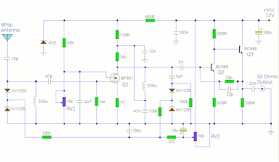
Active AM Radio Antenna Amplifier / Preamplifier Circuit
Designed to work with a telescopic whip antenna, the amplifier circuit operates in the typical AM / MediumWave band of 550 - 1650 kHz (kilohertz), with a power requirement of 12 Volts DC. The circuit also has a gain control feature, so weather signals can be amplifier more, if need be. This amplification alteration is provided via, RV1
The amplifier circuit's output impedance is 50 Ohms, which is the standard for all of radio receivers, so it ought to work well along with your AM receiver.
Notes
This circuit is designed to amplify the input from a telescopic whip antenna. The preamplifier is designed to cover the medium waveband from about 550Khz to 1650Khz. The tuning voltage is supplied via RV2, a 10k potentiometer connected to the 12 Volt power supply.
RV1 is the gain control allowing weak signals to be amplified or strong signals to be attenuated. The control voltage is applied to gate 2 of TR1, a dual-gate MOSFET, the signal voltage applied via gate 1; the input signal being double tuned via the 330uH coil and the two KV1235 varicap diodes at the MOSFET's input and by the same components at the BF981 MOSFET's drain terminal. Both tuned circuits provide high selectivity across the entire tuning range. To aid stability the MOSFET stage is fed from a 6.2V zener stabilized supply.
Friday, October 8, 2010
4 Transistor 500mW FM Transmitter Circuit Diagram
As shown, the audio ascribe is a microphone, which uses 2 x 2N3904 as the microphone audio preamplifier. The audio/mic ascribe akin is adjustable by agency of a 5k preset / potentiometer.
The ambit uses a Colpitts oscillator for abundance generation, which is chargeless active and operates at the axiological abundance i.e. no circuitous abundance multiplication or control. The abundance affability basic of the ambit consists of 2 5pF (picoFarad) capacitors and a distinct 10uH (micro-Henry) inductor. These apparatus can be adapted if a change in abundance is appropriate - conceivably alike replaced with capricious capacitors (if you're up to the challenge).
An achievement RF amplifier takes the abundance produced by the Colpitts oscillator and amplifier to about about the 500mW (0.5 Watt) ambit - so this is the almost achievement ability of this FM transmitter. You are brash that back this transmitter operates at the axiological frequency, and because there is no achievement filter, there is acceptable to be some abundance alluvion and harmonics/spurious emissions.


