Thursday, October 27, 2011
Doorbell Sound with CD4001 CD4060

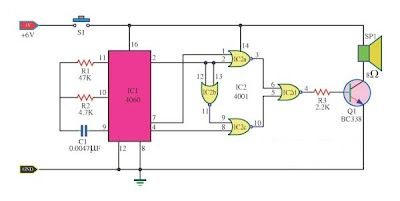
The doorbell sound circuit was two-tone sound. With the switch S1. working of the circuit, IC1 is a frequency division circuit, and a sound frequency generator came out.by C1, R1 is the frequency generator.
This audio signal from pin 7 and pin 4 to pin 1 and pin 8 of the IC2a, IC2c respectively. The IC2b of a frequency converter to control IC2c.When control signal during the low (Low) 1.25 kHz frequency coincides with IC2a.At same time, the control signal is in a high state IC2b (high) , 300 Hz frequency IC2c parties. Output on pin 3 of low IC2a under the same conditions, production and IC2c IC2a IC2d.Which is sent to act as a signal and the output transistors act as switches Q1 and tones amplifiers.The can be heard as two strokes. R3 acts as a volume, add more value to make the softest sound, but softer, a source of 6 volts.
This audio signal from pin 7 and pin 4 to pin 1 and pin 8 of the IC2a, IC2c respectively. The IC2b of a frequency converter to control IC2c.When control signal during the low (Low) 1.25 kHz frequency coincides with IC2a.At same time, the control signal is in a high state IC2b (high) , 300 Hz frequency IC2c parties. Output on pin 3 of low IC2a under the same conditions, production and IC2c IC2a IC2d.Which is sent to act as a signal and the output transistors act as switches Q1 and tones amplifiers.The can be heard as two strokes. R3 acts as a volume, add more value to make the softest sound, but softer, a source of 6 volts.
Class A MOSFET Amplifier 2SK1058

This is simple class A MOSFET amplifier 2SK1058 used in the circuit. It is easy to do, you should use a 24V supply volt at high current. using amplifier with Class A tube preamp based on 12AU7. It produces the purest sound. I have no idea of the levels of distortion, but has a very fine and delicate texture quality. With only one watt speaker output should be used efficiently. Lower is better than expected and the stage design of the units of my 12 "base 63L 3-way speakers with ease.
Monday, October 10, 2011
Battery Charger using LM317 Regulator
This Battery Charger is very similar to the universal charger that uses the constant current load. But this is much simpler to build and can be built using only two parties, the LM317 regulator and resistance. The use of diode D is for protection against short circuits. Capacitors C1 and C2 is good voltage regulation. Resistance R2 operates a dummy load when the battery is disconnected. The idea of this magazine is the output current is equal to 1.2 V, divided by the value of R1.
Part List:
LM317
R1 - see the values in table below
R2 - 2.2 kilo-ohms 1/4W
C1,C2 - 47uF/25V, or any value will do, the higher the better
D - 1N4001 or any similar diode at-least 1A rated
Part List:
LM317
R1 - see the values in table below
R2 - 2.2 kilo-ohms 1/4W
C1,C2 - 47uF/25V, or any value will do, the higher the better
D - 1N4001 or any similar diode at-least 1A rated
1,5V Simple FM Transmitter
This simple FM (frequency modulation) transmitter is powered only by a 1.5V battery and uses only one frequency of this transmitter transistor.The is controlled by the LC resonant circuit and operates from 80 to 110 MHz
The inductor L1 is 8 turns of wire wound magnetic No. 22 with diameter of 4 to 5 cm or the diameter of a pencil. The antenna is a 6-inch cable connected to the copper half of the L1 inductor.Other parts are not critical and can be replaced by their nearest value. Resistance 1 / 4 watt ceramic capacitor type and, except for electrolytic capacitor 10uF. 5-60pF capacitor is a type of court or variable rate.
The inductor L1 is 8 turns of wire wound magnetic No. 22 with diameter of 4 to 5 cm or the diameter of a pencil. The antenna is a 6-inch cable connected to the copper half of the L1 inductor.Other parts are not critical and can be replaced by their nearest value. Resistance 1 / 4 watt ceramic capacitor type and, except for electrolytic capacitor 10uF. 5-60pF capacitor is a type of court or variable rate.
Subscribe to:
Comments (Atom)

