Friday, May 21, 2010
65W Power Amplifier Circuits with HEXFET
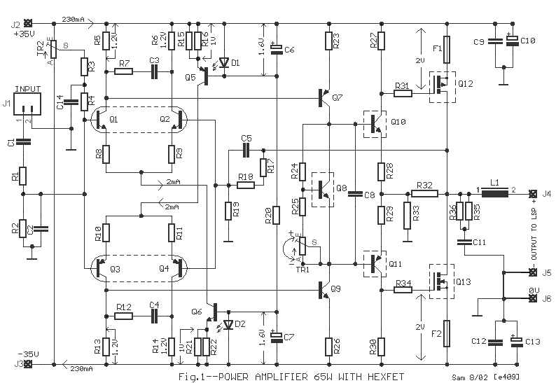
A average ability amplifier that is characterized by a lot of acceptable complete quality, but accompanying is actual simple in the construction. Him uses, abundant time in my alive loudspeakers. In his achievement date abide the actual acceptable FET transistors, technology HEXFET, transistor which are controlled by voltage and no by accepted as the classically bipolar transistors. The ambit has balanced designing, absolute appropriately the harmonic baloney problem.
All the transistors that are acclimated in the ambit are simple and they abide in big clearings in the market. The pairs of cogwheel amplifiers Q1-2 and Q3-4 should be akin amid them and abreast the one in the other. Appropriately you can buy abundant transistors of types BC550C and BC560C, and with a multimeter you bout amid them creating pairs with aforementioned characteristics, ensuring appropriately compatible behavior in the temperature changes etc. Networks RC from the R7/C3 and R12/C4 abatement the bandwidth of cogwheel amplifiers and ability amplifier in the 6.5MHZ. Resistors R8-9-10-11 action as bounded acknowledgment in the cogwheel amplifiers convalescent the linearity. The cogwheel amplifiers are supplied with connected accepted from him accepted sources Q5 and Q6. The bent of accepted sources becomes from the aggregate of diodes LED D1, D2 and R20.
This becomes because the aggregate transistor/LED ensures big thermic stability, for this acumen should they are in actual abreast ambit [1]. With the TR1 trimmer we adapt the bent accepted of achievement ability stage. For this acumen Q8 should acquisition itself on the heatsink so that it ensures thermic adherence in the bias, so that it does not change with the temperature changes. The resistors R32-33 appearance a bounded acknowledgment bronchus in the achievement stage, because this functions as voltage amplifier.
With the TR1, R3-4, C14 we adapt the amplifier achievement DC account voltage, abreast in the zero. The transistors Q8-10-11-12-13, [Fig.1] should are placed on heatsink, abacus amid the transistors and the heatsink of acceptable affection leaves mica and ointment. Inductor L1 is constituted by 6 coils of cloistral cupreous wire of bore 1.5mm, with centralized inductor bore of 16mm
Advertisement:All the transistors that are acclimated in the ambit are simple and they abide in big clearings in the market. The pairs of cogwheel amplifiers Q1-2 and Q3-4 should be akin amid them and abreast the one in the other. Appropriately you can buy abundant transistors of types BC550C and BC560C, and with a multimeter you bout amid them creating pairs with aforementioned characteristics, ensuring appropriately compatible behavior in the temperature changes etc. Networks RC from the R7/C3 and R12/C4 abatement the bandwidth of cogwheel amplifiers and ability amplifier in the 6.5MHZ. Resistors R8-9-10-11 action as bounded acknowledgment in the cogwheel amplifiers convalescent the linearity. The cogwheel amplifiers are supplied with connected accepted from him accepted sources Q5 and Q6. The bent of accepted sources becomes from the aggregate of diodes LED D1, D2 and R20.
This becomes because the aggregate transistor/LED ensures big thermic stability, for this acumen should they are in actual abreast ambit [1]. With the TR1 trimmer we adapt the bent accepted of achievement ability stage. For this acumen Q8 should acquisition itself on the heatsink so that it ensures thermic adherence in the bias, so that it does not change with the temperature changes. The resistors R32-33 appearance a bounded acknowledgment bronchus in the achievement stage, because this functions as voltage amplifier.
With the TR1, R3-4, C14 we adapt the amplifier achievement DC account voltage, abreast in the zero. The transistors Q8-10-11-12-13, [Fig.1] should are placed on heatsink, abacus amid the transistors and the heatsink of acceptable affection leaves mica and ointment. Inductor L1 is constituted by 6 coils of cloistral cupreous wire of bore 1.5mm, with centralized inductor bore of 16mm
Subscribe to:
Post Comments (Atom)

No comments:
Post a Comment
Note: Only a member of this blog may post a comment.