Sunday, July 3, 2011
Digital Clock Circuit with T89C51 microcontroller
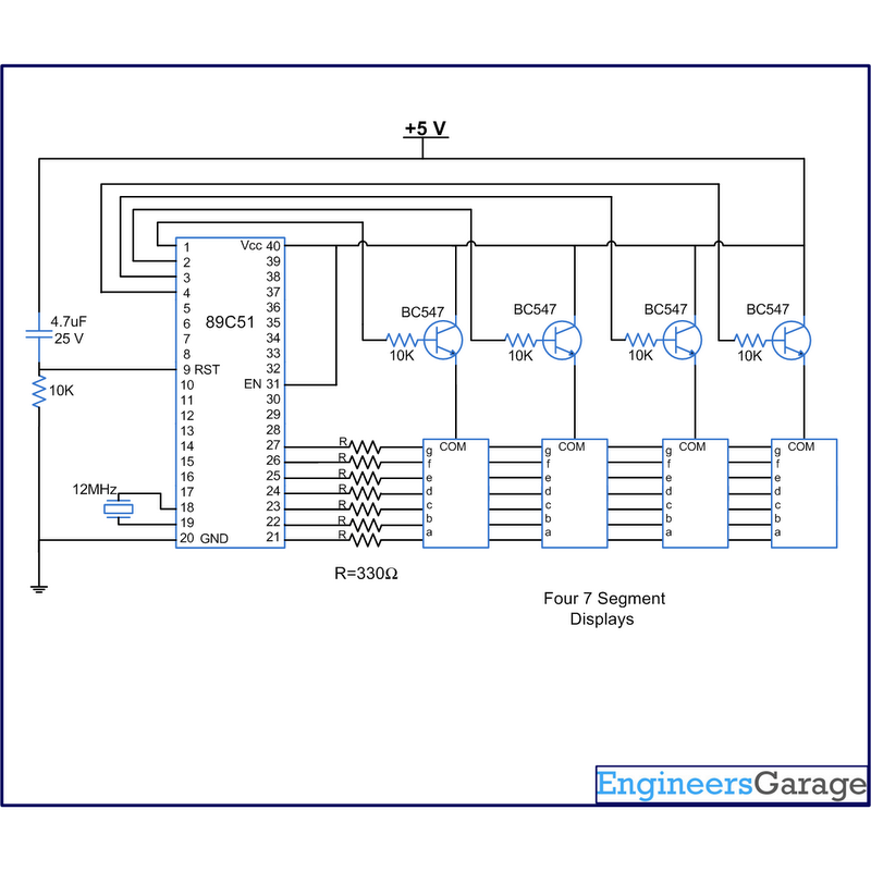
 A digital clock is one that displays time in digital format. The circuit described here shows the time with double-digit "minutes" and two digits 'seconds' in four seven segment displays. The segment of seven switches are interconnected with 8051 microcontroller AT89C51. This circuit can be used in vehicles, homes, offices and many others. At the time of the source Vcc is supplied to this circuit, the clock starts from 00:00. The time is displayed in four segments of 7 (in the common anode configuration) using the notion of multiplexing.
That is achieved by using the timer interrupt (Timer0) of AT89C51 is set to update the 7-segment. The segments are updated several times in the second to be displayed simultaneously. The clock is ticking, which is delayed by one second with single precision. Timer1 is used to produce a one second delay. The pins of information (h) of the many segments are interconnected and get P2 port signal to the microcontroller. The control or enable pin (anode popular) are connected to pins 1-4 of port P1 (P1 ^ 0 - P1 ^ 3).
The number in the fourth section (which shows the unity of the digits 2 º) increases as early as the second, and from 0 to nine. The range in the third section increases immediately after every 10 seconds from 0 to 5. Therefore, the seconds are different sample of 00 to 59. The digit of the variations of the second section after every 60 seconds (one minute) from 0 to nine, etc. So the clock is ticking for an hour and after it resets again
Advertisement:
Subscribe to:
Post Comments (Atom)
No comments:
Post a Comment
Note: Only a member of this blog may post a comment.